On turbine packages, control panel enclosures are often treated like a late-stage detail.
That is usually where problems begin.
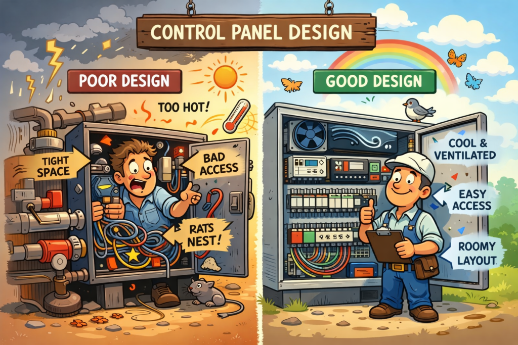
In design reviews, the focus naturally goes to the turbine, piping, structure, and process equipment. While the circuits and control logics are expertly designed, the enclosure gets treated like something that just needs to be mounted and wired without consideration of the physical layout. But in the field, that enclosure often has a bigger impact than people expect. It affects reliability, troubleshooting, maintenance access, and how frustrating the package is to live with over time.
That is something field work makes clear very quickly.
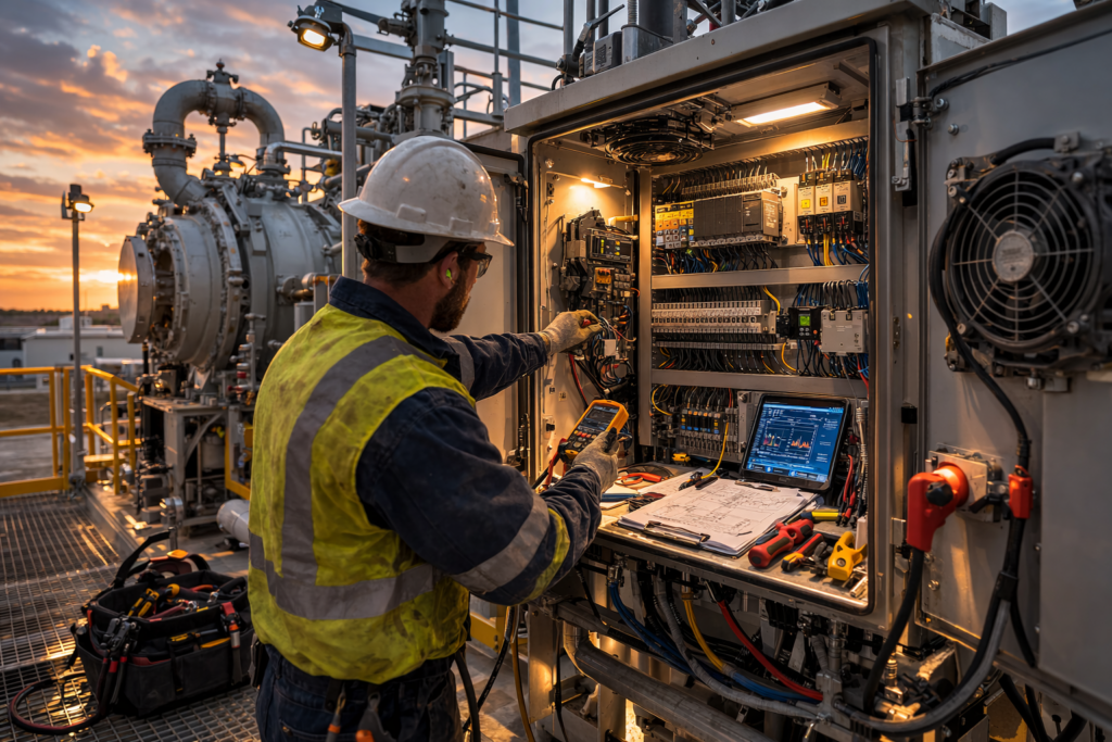
A layout may look fine on paper, but once a technician has to open a panel, trace wiring, replace a component, or troubleshoot an issue in real conditions, weak planning shows up fast. Doors do not open fully. Components are packed too tightly. Heat load was underestimated. Basic service work becomes harder than it should be.
On turbine packages and supporting equipment, better control system and enclosure design starts with better project planning.
That means thinking beyond minimum compliance. It means asking practical questions early. Is there enough room to work safely? Can critical components be reached without tearing into the panel? Has the thermal load been evaluated for actual field conditions? Will this enclosure still be workable after startup, not just during fabrication?
For EPC firms, those decisions affect coordination, layout, and long-term client satisfaction. For plant operators, they directly affect uptime, maintenance efficiency, and how quickly problems can be solved.
This applies beyond turbine packages too. The same issues show up on gas conditioning skids, combustion systems, and other field equipment. The details change, but the principle stays the same: if serviceability is ignored up front, the field will eventually expose it.
A control enclosure is not just a box. It is one of the clearest signs of whether a package was truly planned for real-world use. That is why we believe enclosure design should be approached with the people in mind who will actually operate and maintain the equipment.
In mid-market equipment builds, cost overruns rarely come from exotic materials or cutting corners. They usually come from designs that are technically sound but difficult to build. Tight tolerances where they are not needed. Too many unique parts. Drawings that leave room for interpretation. Each of these decisions adds friction inside the fabrication shop, and that friction shows up as higher cost, longer lead times, and inconsistent quality.
At Polaris Engineering Group, we approach design for manufacturability as a collaboration between the engineer, the fabricator, and the end user. When those three perspectives are aligned early, equipment becomes easier to build, easier to repeat, and easier to support long term.
Where Unnecessary Cost Often Starts
One of the most common cost drivers we see is overly tight tolerances applied across an entire design instead of where they truly matter. Precision has value, but only when it serves performance, safety, or reliability. Applying tight tolerances everywhere increases machining time, inspection effort, and rework risk without improving how the equipment actually operates.
Excessive variation is another hidden cost. When similar parts are designed slightly differently from one another, fabricators lose the ability to batch work. Every unique plate, bracket, or fastener becomes a custom task instead of a repeatable operation. That is where labor costs quietly climb.
Clear documentation plays a major role here. Even a well designed system becomes expensive if the drawings leave room for interpretation. Good drawings reduce questions, reduce assumptions, and keep production moving.
Designing With the Fabricator in Mind
We work with local fabricators whenever possible. Beyond supporting local industry, this often reduces transportation costs, especially for large skids, trailers, or assembled equipment. Shipping heavy or oversized items across long distances can quickly erase any savings gained from lower fabrication rates elsewhere.
That said, national fabricators still have a place when scale or specialization is required. The key is designing equipment that can be built efficiently in either environment. That means avoiding designs that rely on one specific shop process or tribal knowledge.
A manufacturable design should feel familiar to the shop building it. Common materials, straightforward weld details, and logical assembly sequences go a long way toward keeping costs under control.
Reducing Part Count Without Reducing Performance
One of the most effective ways to lower cost is reducing part count. Fewer parts mean fewer drawings, fewer welds, fewer fasteners, and fewer opportunities for error. We routinely look for ways to combine features or eliminate unnecessary components while maintaining strength and function.
Fastener standardization is another simple win. Using a smaller set of bolt sizes reduces purchasing complexity, speeds up assembly, and minimizes mistakes on the shop floor.
For smaller projects, we often design around bulk material thicknesses. Using consistent plate and tube sizes allows shops to buy material in volume and reduces scrap. This approach does not compromise performance when applied thoughtfully, and it often produces cleaner, more consistent builds.
When Poor Manufacturability Becomes a Bottleneck
A good example comes from a large mobile generator set we reviewed that had been designed by a previous firm. The equipment worked, but the documentation and part standardization were poor. Nearly every trailer had unique parts, which made mass production impossible.
Each unit was effectively built from scratch. Fabricators were forced to custom manufacture components on the fly, which increased labor hours, introduced variability, and slowed delivery.
Our role was to step back and rework the design with manufacturability in mind. We consolidated parts, reduced variation, and created a complete drawing package that allowed the shop to produce components in bulk. Once that happened, production stabilized, costs dropped, and the equipment became scalable.
This was not a redesign driven by performance issues. It was a redesign driven by manufacturing reality.
Blending Shop Experience With End User Needs
Polaris sits between the shop and the client. We listen to fabricators who know what works on the floor, and we listen to operators who know how equipment is actually used in the field. The final design reflects both perspectives.
That balance is what makes equipment cost effective to build, reliable to operate, and practical to maintain. Design for manufacturability is not about simplifying for the sake of simplicity. It is about removing unnecessary complexity so the important parts of the design can do their job.
Conclusion
Lowering cost in mid-market equipment builds does not require cutting corners. It requires designing with intent. When tolerances are applied thoughtfully, parts are standardized, drawings are clear, and fabrication realities are respected, equipment becomes easier to build and easier to scale.
Good manufacturable design saves money before the first piece of steel is cut. It also creates equipment that shops want to build and operators trust in the field. That is where long term value is created.
Many equipment failures look sudden, but most of them begin long before anything breaks. Stress concentrations form at small edges or weld transitions. Vibration builds in places that do not seem important at first. Flow inside a pump or pipe begins to cavitate because the geometry was not checked at the right operating point. Problems like these are common in mobile equipment and rotating packages because the loads are constantly changing. They see transport shock, start and stop cycles, thermal shifts, and operating conditions that are never as clean as the specification sheet.
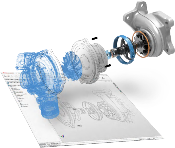
This is where simulation earns its keep. FEA and CFD give you a clear look at how equipment behaves under real conditions. You cannot see these patterns by eye and you cannot measure them during design. The payoff comes from catching issues while the equipment is still on a screen rather than on a truck or on a well site.
1. The Hidden Problems That FEA Reveals Early
In many mobile systems, the failure modes are not dramatic. They come from small details like:
sharp transitions that create stress risers
pipe runs that are too rigid and transfer vibration into pumps or motors
brackets that fatigue slowly because of repeated transport vibration
bolt groups that load unevenly
flow paths that create cavitation inside a pump housing
In harsh environments, these small issues combine until something cracks, leaks, loosens, or vibrates itself apart. Simulation is not about making a design perfect. It is about finding the weak spots before they become maintenance problems.
A good example comes from a pump skid we evaluated. The piping looked clean and correct in CAD, but FEA showed stress intensification at several points because of combined operating loads and transport loads. The solution was simple. We replaced rigid connections with flexible connectors to isolate vibration. A small design change prevented a likely failure, extended equipment life, and avoided unplanned downtime in the field.
2. Why Mobile Units and Rotating Packages Benefit the Most
Stationary systems usually see steady loads. Mobile units do not. They are lifted onto trailers, hauled across uneven roads, set down on imperfect pads, and exposed to constant vibration from nearby equipment. Rotating packages add another layer of complexity because they generate their own vibration patterns and phase relationships.
Simulation helps by revealing how these combined loads interact. For example:
a skid frame that looks stiff in CAD may twist enough during transport to change pump alignment
a pipe that seems properly supported may amplify vibration at certain frequencies
a rotating machine may load bolts or bearing housings unevenly under real operating conditions
These are not dramatic failures. They are the type of issues that raise maintenance costs slowly and shorten the life of equipment. FEA makes these interactions visible so they can be removed early in design.
3. CFD and Flow Behavior Matter More Than Most People Realize
Clients often think of CFD as a high end tool that is only necessary for large or exotic systems. In reality, a small amount of CFD can prevent serious cavitation damage or flow instability in ordinary pump and piping layouts.
CFD can show:
regions of low pressure that may cause cavitation at certain flow rates
velocity patterns that erode elbows or reducers
recirculation zones that cause pump inefficiency
turbulence that leads to vibration in thin wall pipe
A few hours of CFD analysis can save thousands of dollars in equipment repair or weeks of downtime. Cavitation can destroy pump internals quickly. Erosion can weaken a reducer until it fails. These are real costs that far outweigh the cost of a simulation.
4. The ROI Question Should Not Be a Question
One of the biggest misconceptions about FEA is that it is too expensive. The truth is that simulation is already cheap compared to the cost of downtime. Mobile units and rotating equipment packages are revenue producing assets. When they fail, everything around them slows down or stops.
The ROI becomes clear when you look at:
avoided equipment replacement
fewer field repairs
reduced maintenance time
longer equipment life
fewer emergency shutdowns
better reliability during transport
Clients sometimes believe simulation adds extra work. What it really adds is confidence. It removes the unknowns that hide inside a design. It lets the equipment operate as intended instead of reacting to surprises later.
5. Plain Language Matters Because Engineering Should Be Clear
At Polaris we explain FEA and CFD in straight language. These tools show whether a design will behave the way you expect. They help us find weak points, reduce vibration problems, and improve flow behavior. They protect your investment by making sure the equipment can handle real loads, not just ideal ones on a drawing.
The goal is to make simulation feel practical, not mysterious. When our clients understand what the analysis is showing, they make better decisions about strength, materials, geometry, and long term cost.
Conclusion
FEA and CFD are not luxury tools. They are practical methods that keep mobile units and rotating packages working longer in harsh environments. They reveal problems early when they are inexpensive to fix. They help reduce vibration, remove stress risers, improve flow behavior, and extend the life of equipment that is expected to perform in difficult conditions.
Good engineering is not only about producing a design that works. It is about creating equipment that lasts. Simulation is one of the most efficient ways to reach that goal.
Most people think FEED is where a project becomes clear and predictable. In reality, it is also the moment when small site-planning mistakes quietly take root. These early oversights often show up months later during earthwork or fabrication and they can derail a schedule that looked perfectly fine on paper.
At Polaris Engineering Group, we have learned that the most reliable projects come from treating a site as something real and active. The land has natural behavior, especially in regions like West Texas where caliche, uneven topography, and runoff patterns can change quickly. You cannot see all of this from a survey drawing or a digital model, which is why field awareness and flexibility matter so much.
Below is a practical walkthrough of the most common site-planning issues we see and how to avoid them from FEED through fabrication.
1. Misreading Natural Drainage Patterns
This is the single most common issue we catch during FEED reviews. Digital maps can show contours, but they do not always reveal how water actually behaves on the site. Natural drainage is shaped by years of erosion, local topography and even neighboring properties. A site walk often reveals things a topographic model never captured, such as:
shallow erosion paths
low areas hidden by vegetation
ponding in areas that appear flat on a map
minor grade changes caused by nearby construction
Ignoring these clues often leads to more serious issues later, such as water collecting around equipment pads, overloaded culverts or unexpected erosion around structures. Addressing drainage early is one of the easiest ways to prevent costly rework.
2. The West Texas Caliche Problem
Caliche can feel like solid rock one day and behave like an unstable base the next. Many mid-market energy projects in West Texas run into surprises when grading exposes layers of inconsistent density. Common problems include:
settlement under heavy equipment after rain
utility trenches that behave differently across the site
stormwater runoff that changes direction depending on caliche hardness
difficulty compacting pads consistently
These challenges do not mean overbuilding is the answer. A better approach is thoughtful planning. For example, we look closely at subgrade conditions, not just geotech summaries. We also pay attention to how the site behaves after moisture events. The goal is to design pads that perform well not only on paper but in the real environment.
3. What We Look for First During a Site Walk
A physical site walk provides insights that even the best maps cannot. When we walk a new site, we start by looking for three things.
1. The natural layout of the land
We try to let the topography guide the placement of equipment. High points are good for control panels, MCCs or areas that need to stay dry. Lower areas may naturally support drainage features or utility corridors.
2. How the land actually drains
You can learn a lot from soil color changes, small sediment trails or the direction water flowed after the last rain. These subtle details tell us how the site will behave once equipment and foundations are in place.
3. Small but important details that maps miss
We look for things like tire ruts, animal activity, informal pathways used by local personnel or slight grade variations. These small features often reveal how the land is used and how it may need to be adjusted once construction begins.
4. Flexibility Is Essential Because Site Conditions Always Evolve
Some firms treat FEED as a rigid roadmap. We do not. The land changes with weather, construction activity around the site and new information that comes in after initial surveys.
Because of this, Polaris focuses on flexible engineering. Adjustments are not setbacks. They are part of doing the job correctly. This mindset helps our clients avoid unnecessary stress and ensures that the design evolves as the site reveals more about itself.
5. A Real Example of How Adjacent Development Redirected Runoff
In a recent project, everything looked right during FEED. The issue only appeared once construction began. A neighboring property had been graded after our initial survey and that grading completely changed the way stormwater entered the site.
We discovered unexpected runoff flowing across what was supposed to be a controlled pad area. Erosion began forming behind some foundation locations. The site crew had to bring in extra fill, adjust pad elevations and create a new drainage path to protect buried utilities.
This was not a design error. It was a reminder that a site never exists by itself. Adjacent development and constant land changes can reshape conditions in ways that were never shown on the survey.
Conclusion: Good Site Planning Comes From Understanding the Land
Successful FEED and fabrication planning requires more than reviewing drawings. It depends on real observation, simple field experience and the willingness to adapt. When grading, drainage and access decisions reflect the true behavior of the land, the project moves forward with fewer surprises and more confidence.
For mid-market energy companies, these improvements translate into lower costs, faster schedules and better long-term reliability. Good engineering is not just about calculations. It is about understanding how the land wants to work and designing in partnership with it.
Why Modular, Pre-Integrated Design is Reshaping Modern Energy Infrastructure
Processing skids have moved far beyond “a clever way to prepackage equipment.” In mid-market energy projects—especially those balancing lean staffing, regional fabrication partners, and fast-moving capital schedules—skid-based systems have become the backbone of predictable delivery. The real value isn’t just that skids are modular; it’s that they compress dozens of interdependent phases into one coordinated engineering ecosystem.
At Polaris Engineering Group, we see firsthand that when a project shifts from stick-built to skid-based, the timeline doesn’t just shrink—it becomes far more controllable, which is often the true bottleneck in mid-market execution.
Most project delays don’t come from technical complexity—they come from coordination drag:
too many contractors on-site
field crews working around each other
late-arriving equipment
mismatched interfaces between vendors
unexpected interferences or layout conflicts
A skid eliminates dozens of those handoffs by transforming what would be a sequence of site activities into a single, off-site integrated build. Instead of trenching, welding, alignment, mechanical assembly, and electrical runs happening across a 6- to 12-week window, the skid arrives with:
piping pre-routed and supported
vessels, pumps, and exchangers aligned
electrical terminations consolidated
valves, transmitters, and junction boxes pre-tested
structural framework already load-verified via analysis
QA/QC documentation packaged on delivery
2. The Hidden Advantage: Interconnection Discipline Across Phases
The real engineering value comes from forced interconnection discipline—standardized inspection logic, unified QA/QC, shared 3D models, and FEED decisions that carry cleanly into fabrication.
A. Weld maps, NDE sequences, and inspection logic become standardized
Off-site fabrication allows for a unified QA/QC process instead of relying on multiple field inspectors working at different speeds. Every weld, every pressure boundary, and every structural component is produced under one workflow. That uniformity directly improves reliability.
B. Mechanical and electrical teams work on the same 3D model
conduit routing is built around thermal zones
pipe supports account for cable tray loading
instrumentation lines avoid vibration nodes
thermal expansion loops are coordinated with structural deflection limits
C. FEED decisions carry through cleanly into fabrication
A skid locks the FEED logic into the physical equipment:
control philosophies
process flow expectations
utility tie-ins
operational access
maintainability zones
3. Modular Skids Reduce Labor Requirements—But Also Labor Uncertainty
Skid fabrication shifts labor from unpredictable on-site work to stable shop labor:
controlled conditions
repeatable tooling setups
better NDE efficiency
lower rework rates
predictable staffing
4. Integration Planning: Where Experienced Engineers Create Real Value
Good skid engineers design to real-world tolerances, not perfect CAD surfaces. Key considerations include:
tie-in elevations
thermal load path management
vibration isolation and inter-equipment harmonics
equipment access and maintainability
5. Faster Commissioning, Fewer Surprises
A preintegrated skid allows for off-site completion of:
hydrotests
leak checks
instrument loop checks
motor rotation tests
PLC logic verification
FAT and partial SAT activities
6. The Final Advantage: Repeatability & Scalability
Once a skid solves a process challenge, it becomes a repeatable platform that can be deployed across sites, allowing companies to:
standardize operations
reduce downtime variance
simplify training
build site-to-site consistency
improve safety outcomes
reduce total lifecycle cost
Conclusion
Processing skids are not just modular equipment—they’re integrated ecosystems that compress timelines, reduce risk, and improve operational performance. For mid-market energy projects, skid-based design has become a true competitive advantage.
Unlock the Potential of Your Engineering Expertise with Polaris Engineering Group
As a leading Consulting Engineer firm, Polaris Engineering Group is dedicated to delivering exceptional results for our clients. With a team of skilled professionals and a deep understanding of the industry, we provide comprehensive engineering solutions that drive innovation and success. Our expertise spans a wide range of disciplines, allowing us to tackle complex challenges with precision and efficiency.
Elevate Your Engineering Solutions
Innovative Design Strategies
Comprehensive Project Management
Cutting-Edge Technology Integration
Unleash Your Engineering Prowess with Polaris
At Polaris Engineering Group, we believe that the true power of engineering lies in its ability to transform ideas into reality. That’s why we are committed to providing our clients with the expertise, resources, and support they need to achieve their engineering goals. Whether you’re a seasoned professional or just starting out, our team is here to help you unlock the full potential of your engineering expertise.
Uncover the Innovative Solutions of Polaris Engineering Group
As a leading Consulting Engineering firm, Polaris Engineering Group is dedicated to delivering cutting-edge solutions that transform industries. Our team of skilled professionals utilizes advanced technologies and a deep understanding of industry trends to tackle even the most complex challenges. Whether you’re seeking to optimize operations, enhance sustainability, or drive innovation, Polaris Engineering Group is your trusted partner in achieving your goals.
Expertise Tailored to Your Needs
Mechanical Engineering
Structural Engineering
Electrical Engineering
Elevate Your Project with Polaris Engineering Group
At Polaris Engineering Group, we pride ourselves on our ability to deliver innovative solutions that exceed our clients’ expectations. With a proven track record in the Consulting Engineering industry, we are committed to helping John Doe, Jane Doe, and businesses like yours reach new heights. Contact us today at 7777777777 or visit us at 77 triangle drive to learn how we can transform your vision into reality.
Unleashing the Power of Engineering Expertise: Polaris Engineering Group’s Consulting Mastery
At Polaris Engineering Group, we are more than just a team of seasoned consulting engineers – we are visionaries who transform the impossible into reality. With a deep understanding of the industry and a relentless pursuit of excellence, we guide our clients through the most complex engineering challenges, delivering innovative solutions that drive tangible results.
Elevating Your Engineering Endeavors
Comprehensive Consulting Services: From initial concept to final implementation, our team of experts provides end-to-end consulting support, ensuring seamless project execution.
Innovative Problem-Solving: Drawing on cutting-edge industry insights and a wealth of experience, we devise tailored solutions that push the boundaries of what’s possible.
Unparalleled Reliability: With a steadfast commitment to quality and client satisfaction, we consistently deliver exceptional results, earning the trust of our valued partners.
Discover the Polaris Difference
At Polaris Engineering Group, we are more than just a consulting firm – we are your trusted partners in engineering excellence. Discover how our expertise can elevate your next project and propel your business to new heights of success. Contact us today to explore the limitless possibilities.